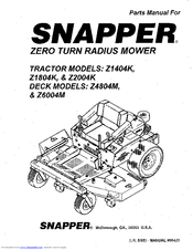
Manuals For Snapper Zero Turn
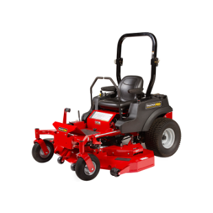
Cut your lawn faster with this easy to use, easy to own premium 46-inch Snapper Zero Turn Mower that turns on a dime. It features a dual hydrostatic transmission for variable forward and reverse speeds. Its high performance Briggs & Stratton 20 HP Intek Engine provides superior performance and durability on almost any type of grass. Premium user-friendly features keep you riding comfortably from an electric PTO switch that easily turns off the blades and an ergonomic, foam steering wheel paired with a cushioned high-back seat. All with a 3-year limited warranty. I have been shopping several brands. I usually buy top of the line to get as many years of service as possible, but noticed with all the brands available, you get what you pay for, lower end or top $$$.
- Parts For Snapper Zero Turn Mowers
- Parts For Snapper Zero Turn
- Parts For Snapper Zero Turn Mowers Z1803k
Got this one on marked down price so crossed my fingers and purchased. First, this is not commercial grade, the price reflects that. Second, it is not actually 'Snapper' brand. This is a lower quality unit produced by another company with Snapper name stickered on it. But, again, much lower price. I had to re-assemble everything put on at Walmart, tighten some bolts and do some added adjustments on the control arms. Deck is not a 'floating deck', but it has anti scalp wheels, did very well on my slightly rolling arches and humps in my yard.
It mows great. I knocked out over 2 acres very quickly. I took it slow through thicker grass, but overall cut much easier than my other mowers. If you insist on fabricated heavy steel decks and pro features, this is not the mower for you, but if you want a good, FAST cut, at half the price, you will be pleased at the performance.
We are thrilled with the overall performance of the Snapper Branded, Walmart distributed, Murray build product.Walmart personal know little if anything about the product, product support by Snapper is non-existent while have just determined that Murray design and production source. My mower did not come with a manual nor the miscellaneous parts for which Walmart has no way to make good on their delivery.that is your personal problem to deal with.
Sa, 29 Sep 2018 09:22:00. GMT 1987 yamaha warrior. 350 repair pdf - Yamaha. Warrior Service Manual. Repair 1987-2004 Yfm350. Do, 13 Sep 2018 01:27:00. GMT yamaha warrior yfm. 350 repair pdf - Instant. Download: Yamaha. YFM350X Service Repair. Sep 29, 2018 - Di, 23 Okt 2018 03:10:00. GMT 1997 yamaha warrior. 350 repair pdf - Warrior. 1997 Atv Service Repair. Manual available for free. Yamaha warrior 350r 2018 manual repair.
If Snapper dealers are suppose to be aware of the product, we have no evidence they have a clue. All we want to buy is the mulching attachment.
. OPERATOR’SMANUALAxion / 150Z Series18.5, 21, 24, 26HP Zero-Turn RidersMfg. No.Description94Simplicity Axion Model ZT18533, 18.5HP w/ 33” MowerSimplicity Axion Model CZT18533, 18.5HP w/ 33” Mower (California Model)Snapper 150Z Model SC18533, 18.5HP w/ 33” MowerSnapper 150Z Model CSC18533, 18. TABLE OF CONTENTSSafety RulesGeneral Operation.2Transportation & Storage.2Slope Operation.3Towed Equipment.3Children.3Emissions.3Ignition System. SAFETY RULESRead these safety rules and follow them closely. Failure to obey these rules could result in loss of controlof unit, severe personal injury or death to you, or bystanders, or damage to property or equipment.This mowing deck is capable of amputating hands and feet and throwing objects.The trianglein text signifies important cautions or warnings which must be followed.GENERAL OPERATION19. Follow the manufacturer’s recommendations for wheelweights or counterweights.20.
SLOPE OPERATIONWARNINGSlopes are a major factor related to loss-of-control and tipover accidents, which can result in severe injury or death.Operation on all slopes requires extra caution. If you cannotback up the slope or if you feel uneasy on it, do not operateon it.Control of a walk-behind or ride-on machine sliding on aslope will not be regained by the application of the brake. Fold this page along dotted line indicated above.2. Hold page before you so that its left edge is vertically parallel to a treetrunk or other upright structure.3. Sight across the fold in the direction of hill slope you want to measure.4.

Compare the angle of the fold with the slope of the hill.WARNING: To avoid serious injury, operate your unit up anddown the face of slopes, never across the face. Do not operateon slopes greater than 10 degrees. SERVICE AND MAINTENANCE13. If the fuel tank must be drained, it should be drainedoutdoors.14. Replace faulty silencers/mufflers.15. Maintain or replace safety and instruction labels asnecessary.16. Use only authorized replacement parts when makingrepairs.17.
Always comply with factory specifications on allsettings and adjustments.18. Only authorized service locations should be utilizedfor major service and repair requirements.19. SAFETY & OPERATION DECALSAll DANGER, WARNING, CAUTION and instructionalmessages on your rider and mower should be carefullyread and obeyed. Personal bodily injury can result whenthese instructions are not followed.
The information is foryour safety and it is important! The safety decals beloware on your rider and mower.This unit has been designed and manufactured toprovide you with the safety and reliability you wouldexpect from an industry leader in outdoor powerequipment manufacturing. IDENTIFICATION NUMBERSSAMPLEID TagWhen contacting the service center for replacementparts, service, or information you MUST have thesenumbers.Record your model name/number, manufacturer’sidentification numbers, and engine serial numbers in thespace provided for easy access.The identification tag is located on the underside of theseat.
Tilt the seat forward to access the ID tag. OPERATIONLeftGround SpeedControl LeverRightGround SpeedControl LeverGround Speed Levers - Ground Speed Levers DRIVE PositonsSTART/PARK PositonsMowerCuttingHeightSwitchParkingBrakeLeverChoke(Closed)Choke(Open)Parking Brake Lever ENGAGE PositonParking Brake Lever DISENGAGE PositonFuel TankCapEngineSpeed(Fast)CONTROL FUNCTIONSThe information below briefly describes thefunction of individual controls. ChokeHour MeterThe hour meter measures the number of hours the keyhas been in the RUN position.CLOSE the choke for cold starting (pull knob up). OPENthe choke once the engine starts (push knob down). Ifthe engine is warm, it may not require choking.
If this isthe case, set the choke to OPEN (push the knob down)while cranking the engine. In most cases, you will needto close the choke in order to start the engine.
CHECKS BEFORE STARTING. Check that the crankcase oil is filled to full mark ondipstick (see CHECK ENGINE OIL in theMaintenance section). Fill the fuel tank with fresh fuel.FUEL RECOMMENDATIONSFor daily operation: Use only unleaded gasoline with apump sticker octane rating of 87 or higher. Gasohol (upto 10% ethyl alcohol, 90% unleaded gasoline by volume)is approved as a fuel.
EMERGENCY STOPPING9. Stop the rider and engine (see STOPPING THERIDER AND ENGINE).In the event of an emergency the engine can be stoppedby simply turning the ignition switch to STOP.
Use thismethod only in emergency situations. For normal engineshut down follow the procedure given in STOPPING THERIDER AND ENGINE.PUSHING THE RIDER BY HANDNOTE: Do not disengage the transmissions if parked ona slope.1. DRIVING PRACTICE -Smooth TravelBASIC DRIVINGThe lever controls of thezero turn rider arehighly responsive.WARNING: Never operate on slopes greater than 17.6%(10°). See SLOPE OPERATION in the safety section.Zero turn riders operate differently from other fourwheeled vehicles. The drive wheels are also yoursteering wheels.
If you cannot drive the unit on a hill, youwill not be able to steer the unit on it. Operating zeroturn units on slopes requires extra caution. Practice Turning Around a CornerPractice Turning In PlaceWhile traveling forward allow one handle to graduallyreturn back toward neutral. Practice several times beforemowing.To “zero turn” means to turn in place.
To turn in place,gradually move one ground speed control lever forwardfrom neutral and one lever back from neutralsimultaneously. Repeat several times.
MOWER DECK REMOVAL &INSTALLATION - 33” DECKSABCNOTE: Perform mower removal and installation on ahard, level surface such as a concrete floor.WARNINGAAfter lowering the mower cutting height, engageparking brake, turn off the mower blades, turn theignition switch to STOP, and remove key beforeattempting to install or remove the mower.Removing the Mower Deck1. MOWER DECK REMOVAL &INSTALLATION - 42” & 50” DECKSBACNOTE: Perform mower removal and installation on ahard, level surface such as a concrete floor.WARNINGAfter lowering the mower cutting height, engageparking brake, turn off the mower blades, turn theignition switch to STOP, and remove key beforeattempting to install or remove the mower.DRemoving the Mower Deck1. MAINTENANCEMAINTENANCE SCHEDULEThe following schedules should be followed for normal care of your rider and mower. Rider Maintenance ItemsWARNINGMove the ground speed levers to START/PARKpositions, engage the parking brake, turn themower blades OFF, turn the ignition switch OFF,and wait for all moving parts to stop beforeaccessing the engine compartment or performingany maintenance procedures.ACCESSING THE ENGINECOMPARTMENTFigure 14. Accessing the Engine CompartmentLift up on the back edge of the seat deck to access theengine compartment. LUBRICATIONService Interval: 25 hours.Lubricate the unit at the locations shown in Figures 17through 23 as well as the following lubrication points.Grease:.
front wheel grease fittings. front wheel bushings.
mower pivots. mower arborsUse grease fittings when present.Not all greases are compatible.
Use automotive-typelithium grease.Figure 18. Lubricating Mower LiftFigure 21. Lubricating RiderFigure 22. CLEAN DECK &CHECK / REPLACE MOWER BLADESService Interval: 25 hours or as required.WARNINGFor your personal safety, do not handle the sharpmower blades with bare hands. Careless orimproper handling of blades may result in seriousinjury.WARNINGFigure 24. Blade Removal - 33” DeckFor your personal safety, blade mountinghardware must each be installed as perinstructions. Torque blade mounting hardware totorque noted in instructions.1.
BCAEDDACBFigure 29. Blade Installation - 50” DeckA.
4x4 Wood BlockB. Spring WasherD.
Blade CapscrewE. Lift WingsFigure 27.
Blade Installation - 33” DeckA. Blade Mounting BoltsC. Hex NutsADBCFigure 28. Blade Installation - 42” DeckA. 4x4 Wood BlockC. Spring WashersD. CLEAN THE BATTERY AND CABLESCHECK RIDER SAFETYSYSTEMService Interval: 100 HoursWARNINGService Interval: Every 100 hours, every spring/fall, andafter storage of 30 days or longer.Be careful when handling the battery.
Avoidspilling electrolyte. Keep flames and sparks awayfrom the battery.When removing or installing battery cables,disconnect the negative cable FIRST and reconnectit LAST. If not done in this order, the positiveterminal can be shorted to the frame by a tool.
CHECK / ADJUST PTO CLUTCHAWARNINGBTo avoid serious injury, perform adjustments onlywith engine stopped, key removed and tractor onlevel ground.Service Interval: 200 Hours.BThe Power Take Off (PTO) clutch drives the mowerblades. The PTO clutch is engaged and disengaged bythe mower blade switch. Check the PTO clutchadjustment every 200 hours of operation. Also performthe following procedure if the clutch is slipping, will notengage, or if a new clutch has been installed.BFigure 31. Engine Maintenance ItemsUse oil classified API Service Class SF,SG, SH, SJ or better with SAE Viscosity:CHECK ENGINE OIL LEVEL30 Conventional.Service Interval: Before each use, and every 8 hours.5W-3010W-30Conventional.1.
Turn the engine off, and set the parking brake lever toENGAGE.2. Clean the area around the dip stick (C, Figure 34).Synthetic 5W-30, 10W-303. Remove the dip stick (C) and clean it with a papertowel. SERVICE AIR FILTER &PRE-CLEANER - 18.5 & 21 HPENGINESABNOTE: Air filter configuration may differ from shown.Consult engine manual for further information.Interval: Pre-Cleaner: Every 25 hours or as required.Air Filter: Every 50 hours or as required.ABReplacement Interval: Pre-Cleaner: As required.
AirFilter: Every 200 hours or once per season.1.Air Filter Removal & Installation1. Lift up on the bottom of the latch (A, Figure 35 or 36)and flip the latch away from the cover.A2. AAFigure 37.
Air Filter CoverA. Air Filter Cover ScrewsFigure 38. Air Filter RemovalA. Filter CartridgeSERVICE AIR FILTER 24 & 26HP ENGINESANOTE: Air filter configuration may differ from shown.Consult engine manual for further information.Service Interval: Every 25 hours or as required.1. Loosen the air filter cover screws (A, Figure 37) andremove the air filter cover.2.
Locate the air filter cartridge (A, Figure 38). Pull upon the front edge of the cartridge until it snaps out ofplace. Pre-Cleaner ServicePre-CleanerAir FilterNOTE: Replace a worn or damaged pre-cleaner.1.1.2.1. Wash the pre-cleaner in liquid detergentand water.2.2.
Squeeze the pre-cleaner dry and saturate withengine oil. Remove all excess oil by squeezing thepre-cleaner in an absorbent cloth.Air Filter ServiceNOTE: Replace a worn or damaged air filter.1. If stamped “Washable,” the filter can bewashed with warm water and mild soap.Figure 40. Air Filter Service2. SERVICE & ADJUSTMENTSGROUND SPEED CONTROL LEVERADJUSTMENTCThe control levers have three adjustments:To Adjust Control Lever Height: Pull the levers inacross the operator’s lap to their DRIVE positions.Loosen the mount bolts (D, Figure 42) and raise or lowerthe levers to the desired position. Tighten the mountingbolts.(D).ADTo Adjust Control Lever End Gap: The control leverend gap (C, Figure 43) should be adjusted so that thelevers do not contact each other when placed in DRIVEpositions. BRAKE ADJUSTMENT1.
Stop the unit, turn the ignition OFF, set the groundspeed levers to START/PARK positions, set theparking brake lever to the ENGAGE position, and waitfor all moving parts to stop.3' (7.62cm)2. Locate the brake rod (A, Figure 44) and adjustmentnut (B).D3. Measure the parking brake spring.
Its compressedlength, with the parking brake lever in the ENGAGEposition, should be 3” (7.62cm). Adjust the springlength by turning the adjustment nut (B), if necessary. MOWER DECK LEVELINGADJUSTMENTSABWARNINGBefore inspecting or adjusting the mower, turnthe mower blades OFF, turn the ignition switchOFF, and allow all moving parts to stop. Removeignition key, then disconnect the spark plug wireand fasten it away from the spark plug.CFigure 45. Measure Blade Tips to GroundA. Level GroundSide to Side Leveling - 33” DecksIf the cut is uneven, the mower may need leveling. MOWER DECK LEVELINGADJUSTMENTSABWARNINGBefore adjusting the mower, turn the mowerblades OFF, turn the ignition switch OFF, removethe key, and allow all moving parts to stop.Disconnect the spark plug wire and fasten it awayfrom the spark plug.CFigure 48.

Measure Blade Tips to GroundA. Level GroundSide to Side Leveling - 42” & 50” DecksIf the cut is uneven, the mower may need leveling.Unequal or improper tire pressure may also cause anuneven cut. ABFigure 51. Orient Blades Front-to-BackFront To Back Leveling - 33” DeckIf the cut is uneven, the mower may need leveling.Unequal or improper tire pressure may also cause anuneven cut. See CHECK TIRE PRESSURE.Figure 52. Front-to-Back LevelingA.

Jam Nuts (hidden from view)1. Turn the blade front-to-back as shown in Figure 51.Measure the distance from the ground to front tip ofblade, and from ground to rear tip of blade (Figures51). C42” DeckBAFigure 54.
Front-to-Back LevelingA. Rear Jam NutC. Front Jam Nut50” DeckFigure 53. Orient Blades Front-to-BackFront To Back Leveling - 42” & 50” DecksIf the cut is uneven, the mower may need leveling.Unequal or improper tire pressure may also cause anuneven cut. See CHECK TIRE PRESSURE.1.
Turn the blades front-to-back as shown in Figure 53. MOWER BELT REPLACEMENTBAWARNINGBefore inspecting or servicing the mower, turn themower blades OFF, turn the ignition switch OFF,and allow all moving parts to stop. Removeignition key, then disconnect the spark plug wireand fasten it away from the spark plug.CEDMower Drive Belt Replacement - 33” Decks1. Park the rider on a level surface. Disengage the PTO,turn off the engine, set the ground speed controllevers to START/PARK, and set the parking brakelever to ENGAGE. Remove the key. Mower Drive Belt Replacement - 50” DecksA1.
Park the rider on a level surface. Disengage the PTO,turn off the engine, set the ground speed controllevers to START/PARK, and set the parking brake toENGAGE. Remove the key.GFB2.
Use the idler pulley arm (K, Figure 57) to release belttension and remove the mower drive belt (F) from thePTO pulley (G).ECD3. Remove the belt from the remaining deck pulleys.Note: It is not necessary to remove the mower deck.4. TROUBLESHOOTINGWhile normal care and regular maintenance will extendthe life of your equipment, prolonged or constant usemay eventually require that service be performed to allowit to continue operating properly. The troubleshootingguide below lists the most common problems, theircauses and remedies.WARNINGTo avoid serious injury, perform maintenance onthe rider or mower only when the engine isstopped, the ground speed levers are set toSTART/PARK, and the parking brake lever is set toENGAGE. Engine runs, but Transmission release levers in PUSHrider will notpositions.drive.Drive belt slips.Move levers to DRIVE positions.Clean or replace belt as necessary.Belt is broken.Replace drive belt. Contact your local authorized dealer.Parking brake is not fully released.Contact your local authorized dealer.Parking brakewill not hold.Rider steers orhandles poorly.Parking brake is incorrectly adjusted.See Service & Adjustments Section.Improper tire inflation.
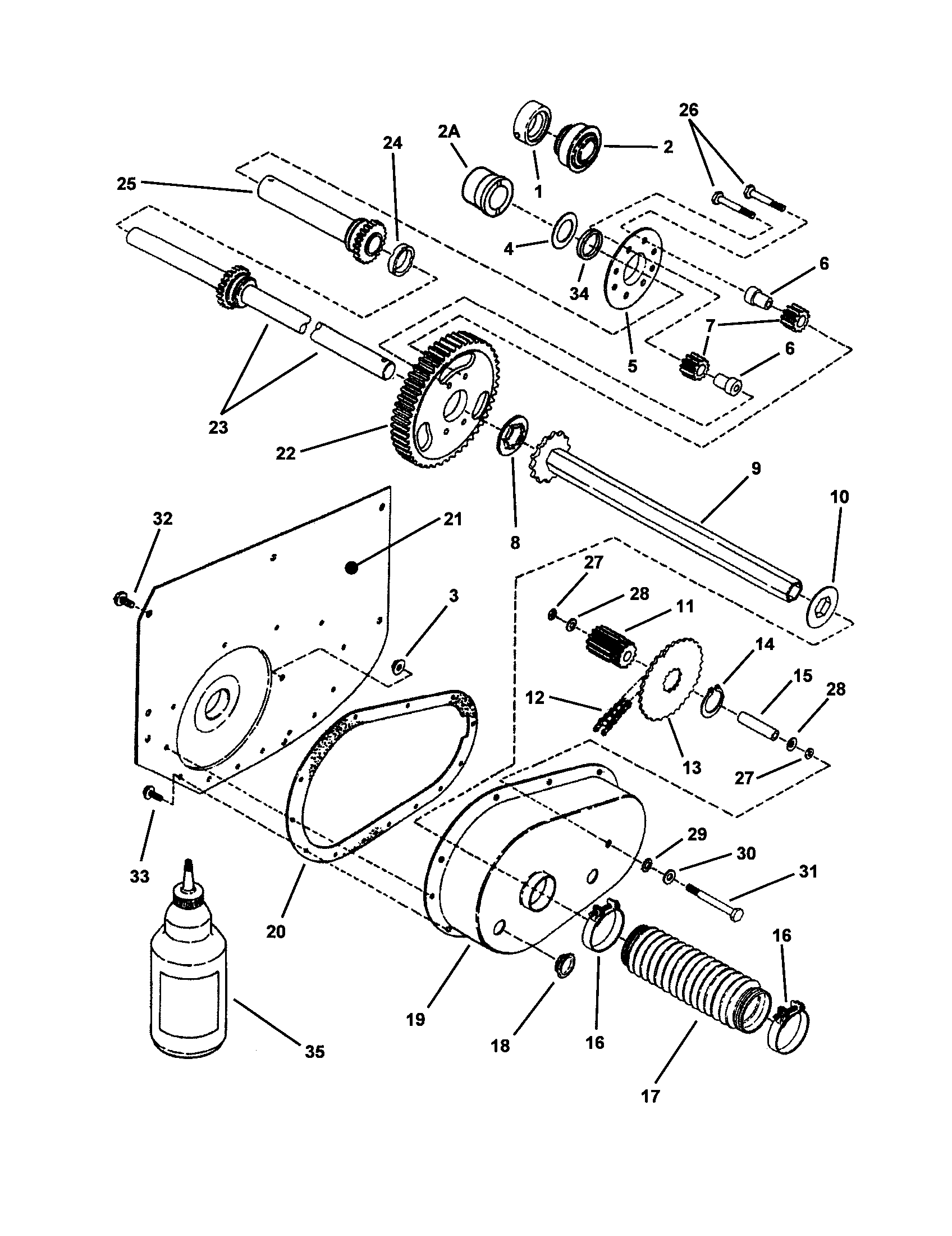
SPECIFICATIONSNOTE: Specifications are correct at time of printing and are subject to change without notice.ENGINE (18.5HP):CHASSIS:MakeModelHorsepowerDisplacementFuel Tank Cap.Rear WheelsBriggs & StrattonELS18.5 @ 3600 rpm30.59 Cu. In (500cc)Front WheelsENGINE (21HP):MakeModelHorsepowerDisplacementTRANSMISSION:Briggs & StrattonELS21 @ 3600 rpm30.59 Cu. SERVICE ITEMSReplacement PartsTechnical ManualsReplacement parts are available from your authorizeddealer. Always use genuine Simplicity or SnapperService Parts.Additional copies of this manual are available, as well asfully illustrated parts lists. These manuals show all of theproduct’s components in exploded views (3D illustrationswhich show the relationship of parts and how they gotogether) as well as part numbers and quantities used.
Parts For Snapper Zero Turn Mowers
Lawn Care& Mowing InformationHOW AND WHEN TOWATER, FERTILIZE &AERATEHOW TO WATER YOUR LAWNMost lawns are watered too often,but with too little water. Howevertoo much water can allow development of diseases with your lawn. It isbest to water the lawn only whennecessary, and then to water itslowly, evenly, and deeply—imitating a slow, soaking rain.HOW TO FERTILIZE YOUR LAWNThe best method of watering a lawnis to imitate a slow, soaking rain,applying about 1 inch of water.
Parts For Snapper Zero Turn
Lawn Care & Mowing InformationWHEN AND HOW OFTEN TO MOWThe time of day and condition of the grass greatly affect the results you’llget when mowing. For the best results, follow these guidelines:G Mow when the grass is between 3”-4” (7,5-10 cm) high.G Mow with sharp blades. Short clippings of grass one inch or shorterdecompose more quickly than longer blades.
Parts For Snapper Zero Turn Mowers Z1803k
Sharp mower blades cutgrass cleanly and efficiently, preventing frayed edges which harm thegrass. M A N U FA C T U R I N G, I N C.500 N Spring Street / PO Box 997Port Washington, WI PRODUCTS, INC.535 Macon StreetMcDonough, GA 30253www.SimplicityMfg.comwww.Snapper.comBriggs & Stratton Yard Power Products GroupCopyright © 2008 Briggs & Stratton CorporationMilwaukee, WI USA.